Component Library Editor
Create and edit schematic / drawing symbols
and footprint / form-factor models.
Schematic Symbol Editor
Layout Footprint / Form-factor Editor

Introduction
The Component Editor is the software tool used to model components such as PLCs, bus-controlled I/O, sensors, data loggers and more.
We continue to grow the list of modelled components supplied with the software.
Attributes such as electrical properties (voltage, current and digital inputs / outputs) can be added to the schematic / drawing symbol.
Serial ports, connectors, wires, cables, switch contacts and other attributes can also be added to the model.
Other attributes such as communication protocols can be created and added. An exhaustive set of protocols are supplied with the software and custom protocols can be created.
Once the model is complete, it can be saved in your library so you can easily drop it into the schematic and layout editors for future projects.
Editor Tabs
The 3 tabs just below the menu bar provide access to editing the component Symbol, the Footprint and also Information about the component.

The
The
The
Component General Information

General information is at the begining of the Information screen.
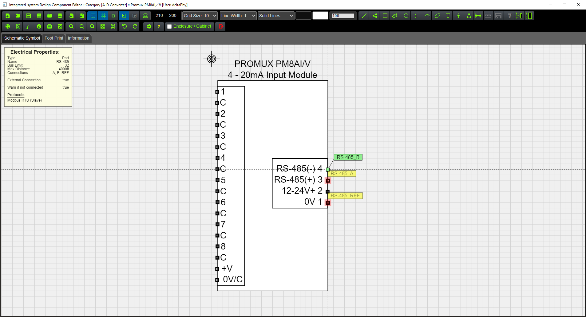
Component Electrical Information

Electrical information is listed below the general information.
A dialog version can be opened using the  toolbar button.
Menu Bar
The menu bar provides easy access to all functions:

Menubar Button
Function


Subsequent Paste operations will place more of these objects.
Footprint information is automatically placed in the footprint view.
NOTE: Undo / Redo or deleting these inserted components in the


Layout Form-factor
This is where you can create and edit component form-factors or 'footprints'.
The
Example Form-factor using Netcom 5G Modem

This example of a component form-factor shows a Netcom Modem.
The  toolbar button has been activated so the schematic symbol is displayed in the bottom right corner of the footprint view.
If you hover your mouse over any electrical connection in the form-factor, it will higlight the corresponding electrical object in the schematic symbol.
Similarly, if you hover your mouse over any connection in the schematic symbol (bottom right corner) it will highlight the corresponding electrical object in the form-factor view.
This helps reconcile electrical objects between the form-factor and schematic symbol.
In this example, the RJ45 Socket in the footprint view is being hovered on which highlights the corresponding RJ45 Socket in the schematic symbol.
Using the magnifier in the footprint view will enlarge the schematic symbol view.
You cannot add or remove electrical objects from the footprint view, this must be done from the Schematic Symbol view.
Cable Components
The image below shows a version of a Cable Component as it is viewed in the Schematic Editor
This example is using an ATMOS-41 weather station.
This is just one way a cable component can be designed. Further down, we will give more schematic diagram options for these components.

This is the same component (ATMOS-41) but it is being viewed from the Layout Editor. All dimensions are in 'real world' units (mm, cm, mil, inches)

Cable Components are made by adding electrical objects and graphics to the Cable Start and Cable End objects.
The electrical and graphic objects at the start of the cable are 'assigned' to the start of the cable by Grouping them to both the Cable Start object and the wires at the start of the cable.
Similarly, the electrical and graphic objects at the end of the cable are 'assigned' to the end of the cable by Grouping them to both the Cable End object and the wires at the end of the cable.
Note: this process is done automatically if Auto-process Cable Objects is selected in User Settings of the Component Library Editor
Example Cable Structure viewed from the Component Library Editor

A cable object consists of a Cable Start object, a Cable End object, a Cable (middle) object where the cable Points / Nodes reside, and a set of Wires for the start of the cable and a set of Wires for the end of the cable.
Another way of designing a cable component is to display no cable in the Schematic Editor while still displaying a cable in the Layout Editor:

This is the same component (Solar Panel) displayed in the Layout Editor which displays the cable.

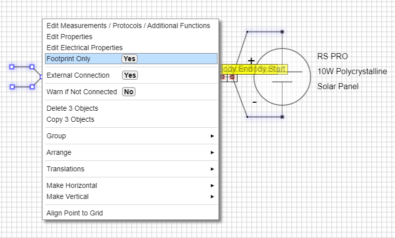
This is achieved by designing the graphics how you want them to be viewed in the Schematic Editor, right-clicking the cable and selecting Footprint Only from the context menu.

Once Footprint Only has been selected, the cable will be displayed with a 'glow' every second or so to indicate it has the 'footpring only' option applied.
You can remove 'footprint only' by repeating the same procedure with the context menu to toggle the feature on and off.
Selecting Footprint Only from the context menu.
Cable Wire Hover Example 1
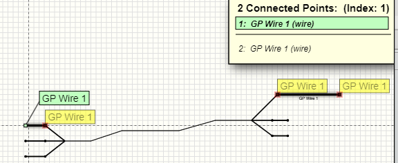
Integrated-system Design wires connect other objects in all editors. Hovering on one wire of a cable will show other connected objects.
In this case, the Overlapping Objects display is showing the wire being hovered on and also the wire at the other end of the cable.
Cable Wire Hover Example 2

In this example the wire at the other end of the cable is connected to a Digital Input object on the Halytech MicroSpider II Logger
The Overlapping Objects display is showing the wire being hovered on, the wire at the other end of the cable and the digital input connected to the other wire.
Creating a Cable Component
This example is using the ATMOS-41 Weather Station manufactured by Meter Group.
Create a Cable Object
Use the  toolbar button to access the Electrical Properties dialog to select / create a suitable cable.
Edit the graphic properties of the cable and wires by right-clicking an object (wire / cable ) and selecting Edit Properties from the pop-up context menu.

The cable width, wire width and color properties have been edited in this example.
Set Wires to Internal
Also, the cable wires should be made Internal (External is false) because they won't be directly accessible in the schematic drawing. This is because in this example, the wires at the start of the cable are connected to the internal sensor circuit, and the wires at the end of the cable are connected to a 3mm jack plug, so are not directly accessible.
Select all wires and right-click to get the context menu. Select External Connection No
This menu item toggles the External Connection state, so the first time you right click the menu item will show: External Connection Yes. Each subsequent click on this menu item will toggle 'Yes', 'No' etc.
Note: this process of making wires internal and grouping cable start / end objects is done automatically if Auto-process Cable Objects is selected in User Settings of the Component Library Editor

Resulting Cable Object

This is the cable so far. Here, we are using the Object Stack to view the objects in the cable within the Component Library Editor.
The cable object is composed of:
Wire objects at the start of the cable:
Wire objects at the end of the cable:
We have named the wire 'tags' to 'ATMOS Power' etc. and colored the wires according to the product datasheet.
Add a Power Input Electrical Object
Add a Power Input object with parameters such as voltage range derived from the product data sheet.
This electrical object has been made Internal using the context menu in the Component Library Editor. This is because there is no external connection to this object except via the cable wire.
Assigning the object to be Internal will hide it in the Schematic Editor, but it will still be available to connect to using the 'ATMOS Power' and 'GND' wires.
We have also selected the Warn if Not Connected option using the context menu so if it is not connected to a suitable power output object in the Schematic Editor, a warning will occur.
The input for this Power Input object is connected to the 'ATMOS Power' wire and the 'REF' (reference) connection is connected to the 'GND' wire.

Add a SDI-12 Port Electrical Object
Add an SDI-12 port object.
This object also has been selected as Internal (External is false) and Warn if Not Connected is selected. This will warn if it is not connected to a suitable port object.
The Protocol, Measurement and Additional Function dialog (PMA) is used to add the SDI-12 Slave protocol and all of the measurements listed.
Click for more information on Applying Protocols and Measurements
Add a Connector Electrical Object
Add a Connector object with parameters such as voltage range derived from the product data sheet.
This version of the ATMOS-41 includes a molded 3mm plug used to connect it to a display / logger.
Note: The connector is not an External object. This is because the 3 connector points will be inside the molded plug and not accessible from the outside.
The 3 connection points will be indirectly accessible via the Connection Point which is the arrow tip. This arrow represents the plug 'barrel'.
Click for more information on Connectors
Attach the connector to the cable end wires.

Style the connector
Add some graphics to style the connector object.
We just used the (Insert Component / Graphic) toolbar button to insert a jack plug graphic.
Note: If you insert the jack plug into the footprint view then the software will switch to the schematic (symbol) view before inserting it. The footprint graphics for this part will be automatically added to the footprint view.
You could select from any of the pre-defined graphics, or just create your own using polygons, lines, rectangles etc.
This was just placed over the connector electrical object:

Resulting Cable End
Now the Cable End has been style with some graphics.

Style the Cable Start with some graphics
We chose to make this cable component look similar to how it looks physically using polylines and rectangles.

Auto Group or Manual Group
All graphic and electrical objects associated with the Start and End of the cable must be grouped together with the cable start / end objects respectively.
This allows the start / end objects to be moved together for example if there is a plug on the end of a cable, it will be moved with the cable and if the cable is moved, the plug will move with it.
You have the option of manually grouping the objects (see the steps below to do this). Remember, the schematic (symbol) and footprint objects must be grouped.
The easiest and quickest way to group the start and end objects with the cable start / end is just to save the component at this point.
The software will detect that some (or all) objects are not grouped to the cable and will ask if you want it done automatically.

Clicking 'Yes' will automatically group the schematic and footprint objects and save the component.
The automatic grouping option can be turned on / off (Auto-process Cable Objects) in the user settings of the Component Library Editor.
This function will now also force wires to be internal connections if they are connected to an electrical object.
Manually Group Option
This section shows you how to manually group the objects if you prefer not to use the auto-group feature.
Group the Cable Start Objects

Select all graphic and electrical objects to be associated with the start of the cable and right-click to get the context menu, then selecte Group
You can either use the Object Stack to select the objects by clicking on object stack elements to toggle their selection, or it's much quicker to drag your mouse out over the objects to 'multi-select' them.
Group the Cable End Objects

Select all graphic and electrical objects to be associated with the end of the cable and right-click to get the context menu, then selecte Group
The Cable Component is now complete. You will now be able to move the start and end objects collectively.
To produce the Footprint version, the same procedure applies. You just have to select the
Importing / Exporting Components
Importing a Component
Use the  toolbar button to Import a component.
Clicking this button will display a File Open dialog. Select the component file you want to import.
Once the component has loaded, you may want to click the Save button to store the component in your Custom database.
Exporting a Component
Use the  toolbar button to Export a component as a file.
Clicking this button will display a File Save dialog. Select the file location you want to save the component file to.