Layout Editor
Create physical layouts using enclosures / cabinets,
din-rails etc.
Introduction
The Layout Editor allows components to be arranged within enclosures / cabinets, mounted to din-rails and wire / cable routing.
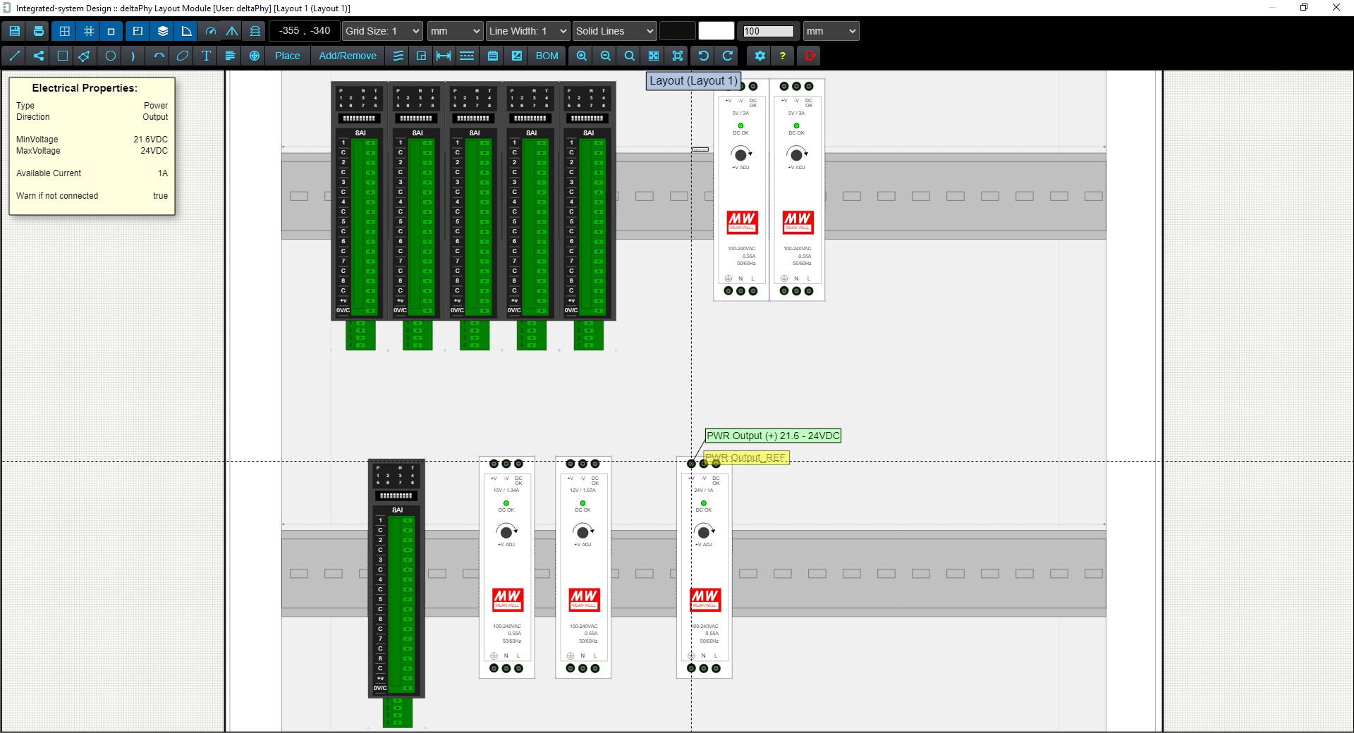
Hovering over components provides the same heads-up displays as the Schematic Editor. Hovering over a component electrical connection (for example a power input or ground connection etc.) will display the electrical object heads-up and also Connection Paths which indicate which other electrical objects should be connected according to the schematic drawing. This is the Layout Editor version of the Guidance System.
For Example, if an RS-232 (Tx) in one component is connected to several other RS-232 (Rx) connections in other components, then hovering on any of them will draw lines or hot-spots to the others if they have been connected in the schematic sheet.
This is helpful as it indicates where the wires should be routed to in the layout.
"Air-wires" between electrical objects indicate where those connections should be wired to. These air-wires can be configured to disappear once a wire has connected the electrical connection points.
Click for more information on Air Wires
Image of Layout Editor showing Airwires and Paths
Click the  button on the toolbar to configure whether paths are lines or hotspots and to access air-wire configuration.
Menu Bar
The menu bar provides easy access to all functions:

Menubar Button
Function


Grid / Display Units
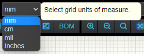
The Grid Units of Measure box selects what measurement units the grid is in.
Options are: mm, cm, mil / thousanth of an inch and Inches.
The grid size can be selected. A grid spacing of 1 inch could be selected, or 10mm / 1 cm etc.
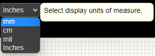
The Display Units of Measure defines how measurements are displayed.
For example, if you selected 1 inch spacing for the grid and mm for the display units of measure, then a dimension object would indicate 25.4mm
If you then selected mm for the display units of measure, the dimension object would indicate 1 inch.
Air Wires
Air Wires are displayed in the Layout Editor and indicate which electrical connections should be wired to other electrical connections according the the schematic diagram.
Air wire display style can be adjusted using the Path Dialog further below on this page.

This image shows the layout for a weather station.
The light grey lines indicate where the connections should be wired to according to the schematic diagram.

This image above is the schematic diagram for the weather station layout.
Hovering on an electrical object point highlights the air-wire in blue to make it easier to see where it should be wired to.
Path Dialog
The path dialog allow you to change the graphic properties of airwires.
This dialog is opened using the toolbar button.
The C key will toggle the Path Style in the layout editor (without having to open this dialog).
Air-wire Style controls the display of air-wires which indicate where electrical objects should be wired to according to the schematic diagram.
Options are:
 Toolbar Button Style for No Path Display
 Toolbar Button Style for Lines Path Display (blue background)
Flash Disconnected
Denotes whether disconnected electrical objects are flagged or not.
'Disconnected' means they are not wired in the layout editor as they are in the schematic editor.

Cable Length Warnings
Cable length warnings apply to cables with 'fixed lengths'. If a depth sensor arrives from the factory with a certain length cable, the Layout Editor will display a warning if the cable's length is stretched beyond that length.
Cable Length Warning in Layout Editor
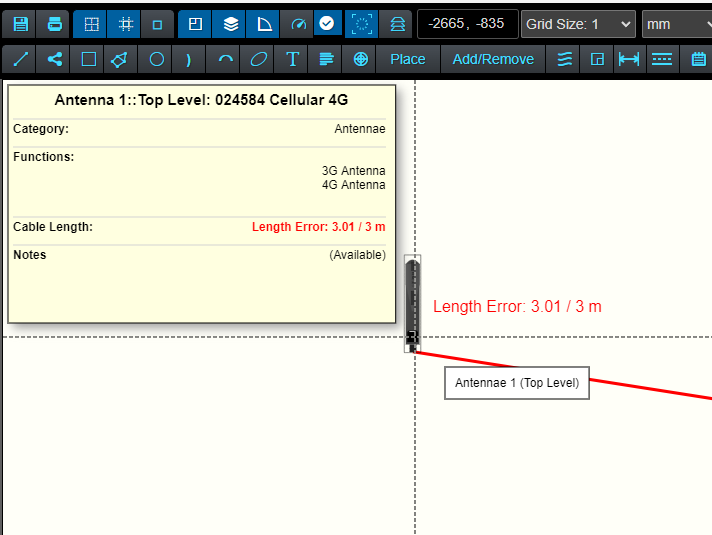
When cables are created in the Component Library Editor you can opt to have a 'fixed length'. This is the length the cable will be from the manufacturer.
The length is used in the Layout Editor to provide a warning if the cable is being stretched longer than this length.
Cable Length Warning In Layout Editor BOM Dialog

In the Layout Editor, any cable that is longer than it's 'fixed length' will be highlighted in red in the BOM and will indicate it's current length compared with it's 'fixed length'.